
|
Pittsburgh Design Services:
|
|
|
|
PDS offers state of the art plate grinding solutions for industry.
Basic Grinding Specification
A. Capable of grinding 20,000 sq.ft./month
Carbon Steel, Thickness: 3/8” – 16”
SS and Nickel Alloys, Thickness: 1/8” – 6”
Titanium Zirconium, Thickness: 1/8” – 6”
Other alloys also
B. Capable of grinding material up to 207” wide x 540” long 16” thick without repositioning material
C. Capable of rapid abrasive belt changes with only minor adjustments required after change
D. Capable of rapid contact wheel changes with only minor adjustments required after change
E. Capable of achieving uniform surface finish Machine must have sufficient structural stability to prevent chatter or other grinding/surface finish defects
F. Belt speed adjustable from 2000 sfpm to 6000 sfpm
G. Contact pressure adjustable from 300 – 500 psi
H. Machine equipped with simple, reliable controls
I. Equipment shall achieve an average run time rate of 70 sq.ft./hr. and achieve a 125 Ra surface finish or better.
Grinding Table – Basic Design Information
-Table to be 25’-0” wide max. x 50’-0” long min.
-Customer provided 9” thick reinforced concrete slab under table area.
-Grinder table to be constructed of steel and concrete grid layout with table raised up above floor 12 inches to allow for encoder set-up – anchored to slab.
-Drain troughs to be 9” wide along both sides and drain into recycling tank at end or center side of table in floor.
-Gantry to run along side beams with ASCE rails mounted on top.
-Grinding lay down surface shall be at top of beams with concrete.
-Grinding direction to be parallel to table side beams.
-2-Heavy duty clamping rails run the length of the table.
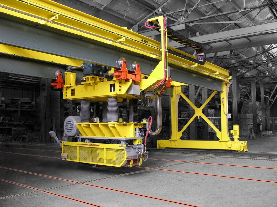
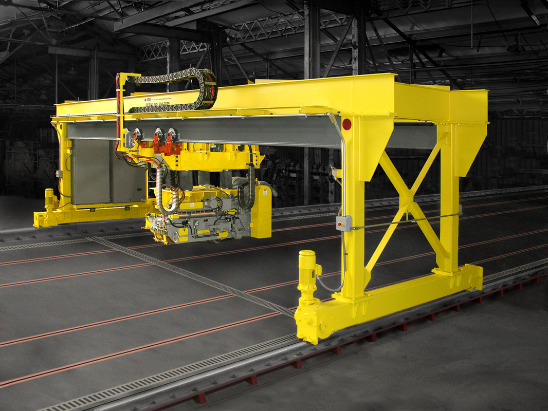
PDS Gantry And Trolley Unit
-Gantry crane structure to consist of a heavy duty double leg structural frame connecting to a double beam patented track bridge structure.
-End trucks to be reinforced structural tubular style with minimum 12” diameter wheels.
-Axles are of the rotating design with spherical roller bearings sized for CMAA Class D Service minimum. Axle construction will be from alloy steel. Wheels are double flange straight tread, machined from alloy steel and heat treated, designed to run on 60 lb. ASCE rail.
G&P Machinery Special Plate Grinding Head
Mounted to the PDS designed trolley frame.
TYPE M
2-40 HP, 1800RPM, TEFC motors.
Belt speed is infinitely variable from 2000-6000 SFPM. (6000 SFPM @ 1800 RPM)
Air tensioning for (4) 4” x 108” abrasive belts.
Four (4) quick-change type contact wheel, pivot mounted with air cylinder to provide grinding pressure, 8” dia. x 4” wide 55 durometer, 1/4:1/4 serration with 1/16” grooves 1” apart at 90 degrees from serration. (approx. sizes)
TYPE S
100HP, 1800RPM, TEFC motors.
Belt speed is infinitely variable from 2000-6000 SFPM
Air tensioning for 12” x 180” abrasive belt.
Quick-change type contact wheel, pivot mounted with air cylinder to provide grinding pressure, 8” dia. X 12” wide 80 durometer, ¼: ¼ serration with 1/16” grooves 1” apart at 90 degrees from serration (approx. sizes).
Coolant Spray System
Coolant will be applied at point of grinder belt contact on plate material to provide a wet grind. Coolant will be applied on each head pulley to clean the belt. PDS system will provide hosing to supply coolant at contact points as well as sump pump to reclaim used coolant from sump. Twin pumps will be provided to supply grinders and feed constant supply to side troughs for washing out.
System Controls & Automation
-An onboard PLC will be supplied to provide automatic indexing of the trolley/grinder head and reversing of bridge travel as soon as grinding pass is complete. The grinding operator will position the grinding head at the beginning of a “run” and punch in parameters to control the gantry speed, belt speed and grinding pressure. Vertical height adjustment will be done manually by the operator as well as the length and width parameters (2 corner point set-up).
-The PLC based system will provide automatic control of traverse of belt sander from home position (near edge of plate) to return position (far edge of plate). Control will enable VFD bridge drive with forward start command at home position and stop drive at far edge of plate as determined by encoder. The belt sander will then be moved a fixed distance across the plate by enabling the trolley for a fixed time interval at a set speed. The bridge drive will then be enabled in the reverse direction. The drive will remain enabled until the near edge of the plate is read as determined by encoder at which time the drive will stop. This completes one pass.
-The trolley will be indexed across the plate as above and then the bridge will start forward beginning the second pass along the plate. This will continue until a preset number of passes has occurred at which time the cycle will be complete.
-Unit will also work in reverse sequence.
-Gantry position location shall be by rack and pinion set-up to position encoder running along the table length.
Note: 200 Amp Main power, 460-60-3, disconnect shall be provided by customer.
A. Capable of grinding 20,000 sq.ft./month
Carbon Steel, Thickness: 3/8” – 16”
SS and Nickel Alloys, Thickness: 1/8” – 6”
Titanium Zirconium, Thickness: 1/8” – 6”
Other alloys also
B. Capable of grinding material up to 207” wide x 540” long 16” thick without repositioning material
C. Capable of rapid abrasive belt changes with only minor adjustments required after change
D. Capable of rapid contact wheel changes with only minor adjustments required after change
E. Capable of achieving uniform surface finish Machine must have sufficient structural stability to prevent chatter or other grinding/surface finish defects
F. Belt speed adjustable from 2000 sfpm to 6000 sfpm
G. Contact pressure adjustable from 300 – 500 psi
H. Machine equipped with simple, reliable controls
I. Equipment shall achieve an average run time rate of 70 sq.ft./hr. and achieve a 125 Ra surface finish or better.
Grinding Table – Basic Design Information
-Table to be 25’-0” wide max. x 50’-0” long min.
-Customer provided 9” thick reinforced concrete slab under table area.
-Grinder table to be constructed of steel and concrete grid layout with table raised up above floor 12 inches to allow for encoder set-up – anchored to slab.
-Drain troughs to be 9” wide along both sides and drain into recycling tank at end or center side of table in floor.
-Gantry to run along side beams with ASCE rails mounted on top.
-Grinding lay down surface shall be at top of beams with concrete.
-Grinding direction to be parallel to table side beams.
-2-Heavy duty clamping rails run the length of the table.
PDS Gantry And Trolley Unit
-Gantry crane structure to consist of a heavy duty double leg structural frame connecting to a double beam patented track bridge structure.
-End trucks to be reinforced structural tubular style with minimum 12” diameter wheels.
-Axles are of the rotating design with spherical roller bearings sized for CMAA Class D Service minimum. Axle construction will be from alloy steel. Wheels are double flange straight tread, machined from alloy steel and heat treated, designed to run on 60 lb. ASCE rail.
G&P Machinery Special Plate Grinding Head
Mounted to the PDS designed trolley frame.
TYPE M
2-40 HP, 1800RPM, TEFC motors.
Belt speed is infinitely variable from 2000-6000 SFPM. (6000 SFPM @ 1800 RPM)
Air tensioning for (4) 4” x 108” abrasive belts.
Four (4) quick-change type contact wheel, pivot mounted with air cylinder to provide grinding pressure, 8” dia. x 4” wide 55 durometer, 1/4:1/4 serration with 1/16” grooves 1” apart at 90 degrees from serration. (approx. sizes)
TYPE S
100HP, 1800RPM, TEFC motors.
Belt speed is infinitely variable from 2000-6000 SFPM
Air tensioning for 12” x 180” abrasive belt.
Quick-change type contact wheel, pivot mounted with air cylinder to provide grinding pressure, 8” dia. X 12” wide 80 durometer, ¼: ¼ serration with 1/16” grooves 1” apart at 90 degrees from serration (approx. sizes).
Coolant Spray System
Coolant will be applied at point of grinder belt contact on plate material to provide a wet grind. Coolant will be applied on each head pulley to clean the belt. PDS system will provide hosing to supply coolant at contact points as well as sump pump to reclaim used coolant from sump. Twin pumps will be provided to supply grinders and feed constant supply to side troughs for washing out.
System Controls & Automation
-An onboard PLC will be supplied to provide automatic indexing of the trolley/grinder head and reversing of bridge travel as soon as grinding pass is complete. The grinding operator will position the grinding head at the beginning of a “run” and punch in parameters to control the gantry speed, belt speed and grinding pressure. Vertical height adjustment will be done manually by the operator as well as the length and width parameters (2 corner point set-up).
-The PLC based system will provide automatic control of traverse of belt sander from home position (near edge of plate) to return position (far edge of plate). Control will enable VFD bridge drive with forward start command at home position and stop drive at far edge of plate as determined by encoder. The belt sander will then be moved a fixed distance across the plate by enabling the trolley for a fixed time interval at a set speed. The bridge drive will then be enabled in the reverse direction. The drive will remain enabled until the near edge of the plate is read as determined by encoder at which time the drive will stop. This completes one pass.
-The trolley will be indexed across the plate as above and then the bridge will start forward beginning the second pass along the plate. This will continue until a preset number of passes has occurred at which time the cycle will be complete.
-Unit will also work in reverse sequence.
-Gantry position location shall be by rack and pinion set-up to position encoder running along the table length.
Note: 200 Amp Main power, 460-60-3, disconnect shall be provided by customer.
Departmental Contact: Raymond Banks - [email protected] - Ext 228